WHITE PAPER
04/2016
A Reference Architecture for Deploying WSO2 Middleware on Kubernetes
By Imesh Gunaratne
Senior Technical Lead, WSO2
Table of Contents
1. An Introduction to Kubernetes
Kubernetes is a result of over a decade and a half experience on managing production workloads on containers at Google [1].Google has been contributing to Linux container technologies, such as cgroups, lmctfy, libcontainer for many years and has been running almost all Google applications on them. As a result, Google started the Kubernetes project with the intention of implementing an open source container cluster management system similar to the one they use inhouse called Borg [1].
Kubernetes provides deployment, scaling, and operations of application containers across clusters of hosts, providing container-centric infrastructure. It can run on any infrastructure and can be used for building public, private, hybrid, and multi-cloud solutions. Kubernetes provides support for multiple container runtimes; Docker, Rocket (Rkt) and AppC.
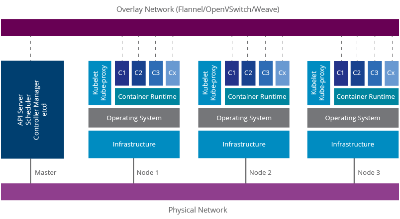
Figure 1: Kubernetes Architecture
A Kubernetes cluster is comprised of a master node and a set of slave nodes. The master includes the Kubernetes
-
API Server
- The API server exposes four APIs; Kubernetes API, Extensions API, Autoscaling API, and Batch API. These are used for communicating with the Kubernetes cluster and executing container cluster operations.
-
Scheduler
- The Scheduler’s responsibility is to monitor the resource usage of each node and scheduling containers according to resource availability.
-
Controller Manager
- Controller manager monitors the current state of the applications deployed on Kubernetes via the API server and makes sure that it meets the desired state.
-
etcd
- etcd is a key/value store implemented by CoreOS. Kubernetes uses that as the persistence storage of all of its API objects.
The nodes include Kubernetes
-
Kubelet
- Kubelet is the agent that runs on each node. It makes use of the pod specification for creating containers and managing them.
-
Kube-proxy
- Kube-proxy runs in each node for load balancing pods. It uses iptable rules for doing simple TCP, UDP stream forwarding or round robin TCP, UDP forwarding.
A Kubernetes production deployment may need multiple master nodes and a separate etcd cluster for high availability. Kubernetes make use of an overlay network for providing networking capabilities similar to a virtual machine-based environment. It allows container-to-container communication throughout the cluster and will provide unique IP addresses for each container. If such a software defined network (SDN) is not used, the container runtimes in each node will have an isolated network and subsequently the above networking features will not be available. This is one of the key advantages of Kubernetes over other container cluster management solutions, such as Apache Mesos.
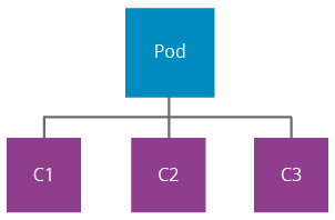
Figure 2: Kubernetes Pod
A pod [2] is a group of containers that share the storage, users, network interfaces, etc. using Linux namespaces (ipc, uts, mount, pid, network and user), cgroups, and other kernel features. This facilitates creating composite applications while preserving the one application per container model. Containers in a pod share an IP address and the port space. They can find each other using localhost and communicate using IPC technologies like SystemV semaphores or POSIX shared memory. A sample composition of a pod would be an application server container running in parallel with a Logstash container monitoring the server logs using the same filesystem.
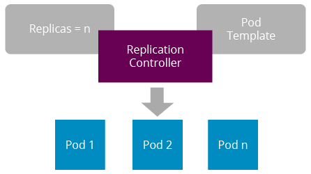
Figure 3: Kubernetes Replication Controller
A replication controller is a logical entity that creates and manages pods. It uses a pod template for defining the container image identifiers, ports, and labels. Replication controllers auto heal pods according to the given health checks. These health checks are called liveness probes. Replication controllers support manual scaling of pods, and this is handled by the replica count.
In reality, software applications fail due to many reasons; undiscovered bugs in the code, resource limitations, networking issues, infrastructure problems, etc. Therefore, monitoring software application deployments is essential. Kubernetes provides two main mechanisms for monitoring applications. This is done via the Kubelet agent:
-
Process Health Checking
Kubelet continuously checks the health of the containers via the Docker daemon. If a container process is not responding, it will get restarted. This feature is enabled by default and it’s not customizable.
-
Application Health Checking
Kubernetes provides three methods for monitoring the application health, and these are known as health checking probes:
-
HTTP GET
- If the application exposes an HTTP endpoint, an HTTP GET request can be used for checking the health status. The HTTP endpoint needs to return a HTTP status code between 200 and 399, for the application to be considered healthy.
-
Container Exec
- If not, a shell command can be used for this purpose. This command needs to return a zero to application to be considered healthy.
-
TCP Socket
- If none of the above works, a simple TCP socket can also be used for checking the health status. If Kubelet can establish a connection to the given socket, the application is considered healthy.
-
HTTP GET
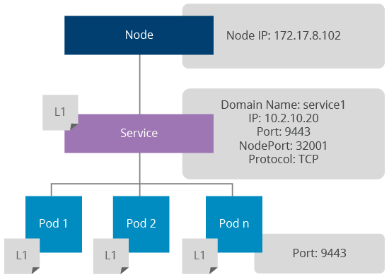
Figure 4: How Kubernetes Services Work
A Kubernetes service provides a mechanism for load balancing pods. It is implemented using kube-proxy and it internally uses iptable rules for load balancing at the network layer. Each service exposes a DNS entry via Sky DNS for accessing the service within the Kubernetes internal network. There are three service types:
-
ClusterIP
- This type will make the service only visible to the internal network for routing internal traffic.
-
NodeIP
-
This type will expose the service via node ports to the external network. Each port in a service will be mapped to a node port and those will be accessible via
<node-ip>:<node-port> .
-
This type will expose the service via node ports to the external network. Each port in a service will be mapped to a node port and those will be accessible via
-
Load Balancer
- If services need to be exposed via a dynamic load balancer the service type can be set to Load Balancer. This feature is enabled by the underlying cloud provider (example: GCE).
This is one of the distinguishing features of Kubernetes that allows users to do a rollout of a new application version without a service outage. Once an application is deployed using a replication controller, a rolling update can be triggered by packaging the new version of the application to a new container image. The rolling update process will create a new replication controller and rollout one pod at a time using the new replication controller created. The time interval between a pod replacement can be configured. Once all the pods are replaced the existing replication controller will be removed.
The below sample kubectl command shows how an existing WSO2 ESB deployment can be updated using a rolling update:
Similarly, an application update done via a rolling update can be rolled back if needed.
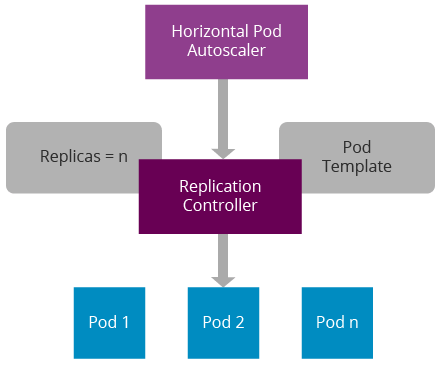
Figure 5: Horizontal Pod Autoscaler
Horizontal Pod Autoscalers provide autoscaling capabilities for pods. It does this by monitoring health statistics sent by the cAdvisor. A cAdvisor instance runs in each node and provides information on CPU, memory, and disk usage of containers. These statistics get aggregated by Heapster and get accessible via the Kubernetes API server. Currently, horizontal autoscaling is only available based on CPU usage, and an initiative is in progress to support custom metrics.
Applications that run on pods may need to contain passwords, keys, and other sensitive information. Packaging them with the container image may lead to security threats. Technically, anyone who gets access to the container image will be able to see all of the above. Kubernetes provides a much more secure mechanism to send this sensitive information to the pods at the container startup without packaging them in the container image. These entries are called secrets. For example, a secret can be created via the secret API for storing a database password of a web application. Then the secret name can be given in the replication controller to let the pods access the actual value of the secret at the container startup.
Kubernetes uses the same method for sending the token needed for accessing the Kubernetes API server to the pods. Similarly, Kubernetes supports sending configuration parameters to the pods via ConfigMap API. Both secrets and config key/value pairs can be accessed inside the container either using a virtual volume mount or using environment variables.
Docker supports mounting storage systems to containers using container host storage or network storage systems [11]. Kubernetes provides the same functionality via the Kubernetes API and supports NFS, iSCSI, Gluster, Ceph, Cinder, or Flocker.
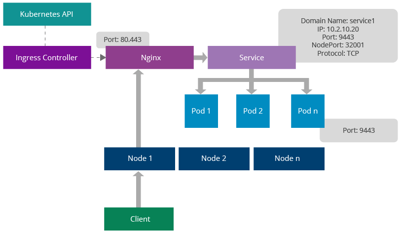
Figure 6: Ingress Controller Architecture
Kubernetes provides a mechanism for adding a proxy server for Kubernetes services. This feature is known as Ingress [3]. The main advantage of this is the ability to expose Kubernetes services via well-known ports, such as 80, 443. An ingress controller listens to Kubernetes API, generates a proxy configuration in runtime whenever a service is changed, and reloads the Nginx configuration. It can expose any given port via a Docker host port. Clients can send requests to one of the Kubernetes node IPs, Nginx port and those will get redirected to the relevant service. The service will do round robin load balancing in the network layer.
The service can be identified using an URL context or hostname;
https://node-ip/foo/, https://foo.bar.com/
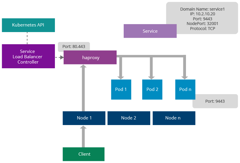
Figure 7: Service Load Balancer Architecture
Similar to ingress controllers, Kubernetes provides another mechanism for load balancing pods using third-party load balancers. These are known as service load balancers. Unlike ingress, service load balancers don’t route requests to services, rather they are dispatched directly to the pods. The main advantage of this feature is the ability to provide sticky session management at the load balancer.
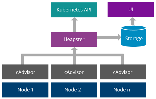
Figure 8: Kubernetes Resource Usage Monitoring System
Kubernetes uses cAdvisor [5] for monitoring containers in each node. It provides information on CPU usage, memory consumption, disk usage, network statistics, etc. A component called Heapster [6] aggregates above data and makes them available via Kubernetes API. Optionally, data can be written to a data store and visualized via a UI. InfluxDB, Grafana and Kube-UI can be used for this purpose [7].
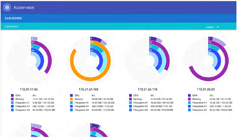
Figure 9: Kube-UI
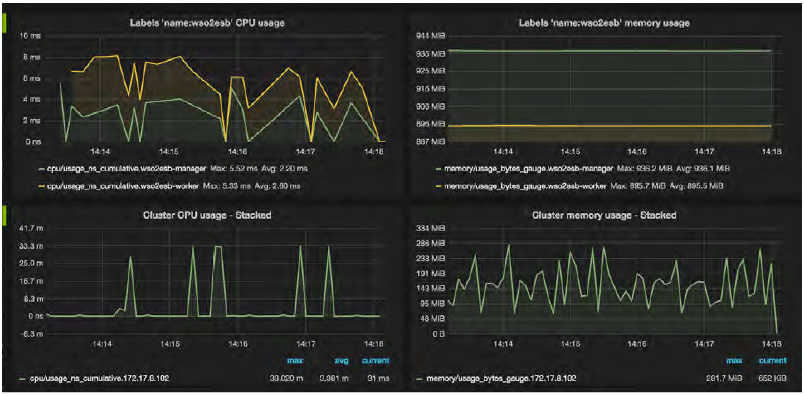
Figure 10: Grafana Dashboard
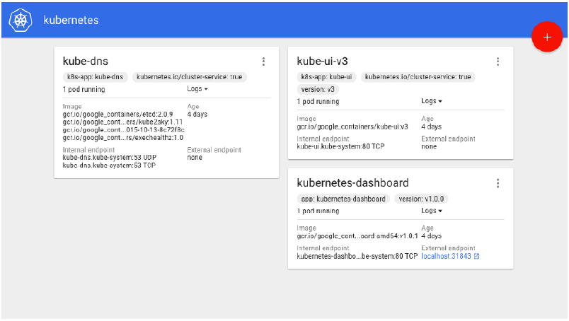
Figure 11: Kubernetes Dashboard
Kubernetes dashboard provides features for deploying and monitoring applications. Any server cluster can be deployed by specifying a Docker image ID and required service ports. Once deployed, server logs can be viewed via the same UI.
WSO2 Carbon 4 based middleware products run on Oracle JDK. According to the Oracle JDK licensing rules, WSO2 is not able to publish Docker images on Docker Hub including Oracle JDK distribution. Therefore, WSO2 does not publish Carbon 4 based product Docker images on Docker Hub. However, WSO2 ships Dockerfiles for building WSO2 Docker images via WSO2 Dockerfiles Git repository.
The above Git repository provides a set of bash scripts for completely automating the Docker image build process. These scripts have been designed to optimize the container image size. More importantly, it provides an interface for plugging in configuration management systems, such as Puppet, Chef, and Ansible for automating the configuration process. This interface is called the provisioning scheme. WSO2 provides support for two provisioning schemes as described below:
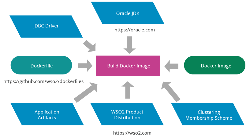
Figure 12: WSO2 Docker Image Build Process Using Default Provisioning
WSO2 Docker images with vanilla distributions can be built using a default provisioning scheme provided by the WSO2 Docker image build script. It is not integrated with any configuration management system, therefore vanila product distributions are copied to the Docker image without including any configurations. If needed, configuration parameters can be provided at the container startup via a volume mount by creating another image based on the vanilla Docker image.
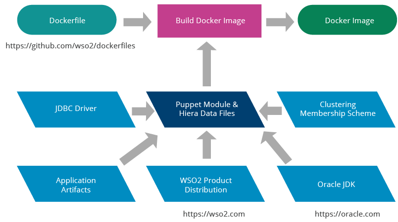
Figure 13: WSO2 Docker Image Build Process with Puppet Provisioning
WSO2 Puppet modules can be used for configuring WSO2 products when building Docker images. The configuration happens at the container image build time and the final container image will contain a fully configured product distribution. The WSO2 product distribution, Oracle JDK, JDBC driver, and clustering membership scheme will need to be copied to the Puppet module.
WSO2 Carbon 4 based middleware products run on Oracle JDK. According to the Oracle JDK licensing rules, WSO2 is not able to publish Docker images on Docker Hub including Oracle JDK distribution. Therefore, WSO2 does not publish Carbon 4 based product Docker images on Docker Hub. However, WSO2 ships Dockerfiles for building WSO2 Docker images via WSO2 Dockerfiles Git repository.
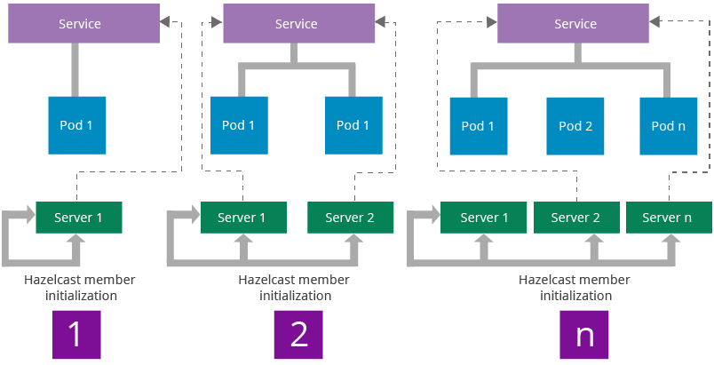
Figure 14: Carbon Cluster Discovery Workflow on Kubernetes
The WSO2 Carbon framework uses Hazelcast for providing clustering capabilities to WSO2 middleware. WSO2 middleware uses clustering for implementing distributed caches, coordinator election, and sending cluster messages. Hazelcast can be configured to let all the members in a cluster be connected to each other. This model lets the cluster to be scaled in any manner without losing cluster connectivity. The Carbon framework handles the cluster initialization using a membership scheme. WSO2 ships a clustering membership scheme Kubernetes to be able to discover the cluster automatically while allowing horizontal scaling.
Multi-tenancy in WSO2 middleware can be handled on Kubernetes using two different methods:
-
JVM Multi-Tenancy
This is the standard multi-tenancy implementation available in Carbon 4 based products. Carbon runtime itself provides tenant isolation within the JVM.
-
Kubernetes Namespaces
Kubernetes provides tenant isolation in the container cluster management system using namespaces. In each namespace a dedicated set of applications can be deployed without any interference from other namespaces.
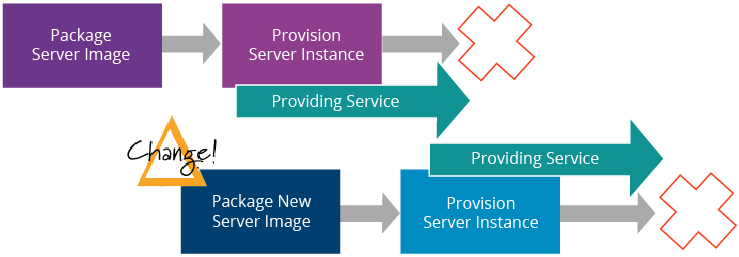
Figure 15: Change Management with Immutable Servers Source: Martin Fowler [9]
Unlike virtual machines, containers package all artifacts required for hosting an application in its container image. If a new artifact needs to be added to an existing deployment or an existing artifact needs to be changed, a new container image is used instead of updating the existing containers. This concept is known as Immutable Servers [9]. WSO2 uses the same concept for distributing artifacts of WSO2 middleware on Kubernetes using the Rolling Update feature.
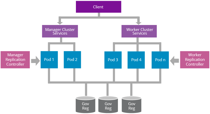
Figure 16: A Reference Architecture for Deploying Worker/Manager Separated WSO2 Product on Kubernetes
WSO2 Carbon 4 based products follow a worker/manager separation pattern for optimizing the resource usage. Figure 16 illustrates how a such a deployment can be done on Kubernetes using replication controllers and services. Manager replication controller is used for creating, auto healing, and manual scaling of manager pods. The manager service is used for load balancing manager pods. Similarly, worker replication controller manages the worker pods and worker service exposes the transports needed for executing the workload of the Carbon server.
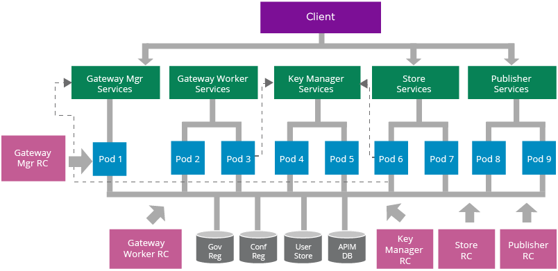
Figure 17: A Reference Architecture for Deploying WSO2 API Manager on Kubernetes
WSO2 API Manager supports multiple deployment patterns [10]. In this example, we have used the fully distributed deployment pattern to explain the basic deployment concepts. Similar to the worker/manager deployment pattern, replication controllers and services are used for each API-M sub clusters; store, publisher, key manager, gateway manager, and gateway worker. Replication controllers provide pod creation, auto healing, and manual scaling features. Services provide internal and external load balancing capabilities.
API artifact synchronization among the gateway manager and worker nodes are handled by rsync. Each gateway worker pod will contain a dedicated container for running rsync for synchronizing API artifacts from the gateway manager node.
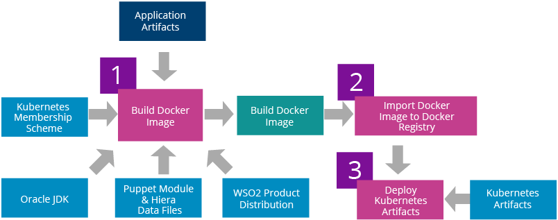
Figure 18: WSO2 Middleware Deployment Workflow for Kubernetes
The first step of deploying WSO2 middleware on Kubernetes is building the required Docker images. This step will bundle WSO2 product distribution, Oracle JDK, Kubernetes membership scheme, application artifacts, and configurations to the Docker images. Once the Docker images are built those need to be imported into a private Docker registry. The next step is to update the replication controllers with the Docker image IDs used. Finally, replication controllers and services can be deployed on Kubernetes.
WSO2 ships artifacts required for deploying WSO2 middleware on Kubernetes. These include the following:
- WSO2 Puppet modules (optional)
- WSO2 Dockerfiles
- Kubernetes membership scheme
- Kubernetes replication controllers
- Kubernetes services
- Bash scripts for automating the deployment
These artifacts can be found in the following Git repositories:
https://github.com/wso2/puppet-modules
https://github.com/wso2/dockerfiles
https://github.com/wso2/kubernetes-artifacts
The Kubernetes project was started by Google with over a decade and half of experience on running containers at scale. It provides a rich set of features for container grouping, container orchestration, health checking, service discovery, load balancing, horizontal autoscaling, secrets & configuration management, storage orchestration, resource usage monitoring, CLI, and dashboard. None of the other container cluster management systems available today provide all of those features. Therefore, Kubernetes is considered the most advanced, feature-rich container cluster management system available today.
WSO2 middleware can be deployed on Kubernetes by utilizing native container cluster management features. WSO2 ships Dockerfiles for building WSO2 Docker images, a Carbon membership scheme for Carbon cluster discovery and Kubernetes artifacts for automating the complete deployment. WSO2 Puppet modules can be used for simplifying the configuration management process of building Docker images. If required, any other configuration management system like Chef, Ansible, or Salt can be plugged into the Docker image build process.
- Large-scale cluster management at Google with Borg, Google Research:
https://research.google.com/pubs/pub43438.html - Pods, Kubernetes Docs: https://kubernetes.io/docs/user-guide/pods
- Ingress Controllers, Kubernetes:
https://github.com/kubernetes/contrib/tree/master/ingress/controllers - Service Load Balancer, Kubernetes:
https://github.com/kubernetes/contrib/tree/master/service-loadbalancer -
cAdvisor, Google:
https://github.com/google/cadvisor - Heapster, Kubernetes: https://github.com/kubernetes/heapster
- Monitoring, Kubernetes:https://kubernetes.io/docs/user-guide/monitoring
- Kubernetes Membership Scheme, WSO2:
https://github.com/wso2/kubernetes-artifacts/tree/master/common/kubernetesmembership-scheme - Immutable Servers, Martin Fowler: https://martinfowler.com/bliki/ImmutableServer.html
- WSO2 API Manager Deployment Patterns
https://docs.wso2.com/display/CLUSTER420/API+Manager+Clustering+Deployment+Patterns - Docker, Manage data in containers:
https://docs.docker.com/engine/userguide/containers/dockervolumes/
For more details about our solutions or to discuss a specific requirement